UPDATE: I have revised the original design and made some changes along the way. An improved Version 2 of the Choke is in place at 2 of my antenna installations and it works very well. Construction details and pictures of the Version 2 Choke, along with some VNA plots and measurements are available on my blog : http://blog.kotarak.net/2009/04/common-mode-choke-ver-20.html
Common-mode current choke is often needed at the antenna feedpoint to stop RF current from flowing back thru the coaxial feedline shield into the shack. It will prevent the coaxial line from becoming a part of the antenna system (to act as a ground radial) and radiate RF energy. The choke presents itself as a high-impedance device to the common mode currents. There are many commercial solutions including the one offered by SteppIR. DX Engineering also makes common-mode current chokes designed specifically for vertical antennas.
I needed one that is equipped with Type-N connectors and it is also capable of handling QRO power levels. After some looking around, I decided to build my own version. Such choke is fairly easy and inexpensive to build and it is a fun project too. My choke cost me less than $30 and about 2 hours of build time. I found on the Internet an excellent document on the common-mode chokes by W1HIS. I used this research and ideas as a base when designing my version of the Choke.
The bill of materials included a weather-proof electrical junction box from Home Depot, 2 bulkhead female Type-N connectors, stainless steel hardware (8 screws, 16 nuts, 12 washers, 8 lock-washers), some de-soldering braid, non-corrosive RTV silicone, 4 small gauge ring connector terminals, about 5' of Times Microwave LMR-240 coaxial cable and 18 ferrite toroids made by FairRite (Part# 2643801002) - mix 43, OD 28.5mm, ID 18.5 mm, H 7.5mm.
I selected the Times Microwave LMR-240 because of the small size (same as RG-8X), lower loss (solid center conductor), better shielding (bonded aluminum foil in addition to the braid) and also better power ratings. Overall, this cable is a better version of the popular RG-8X.
The mix 43 toroids are preferred for HF chokes and they work well on the higher HF frequencies (10 meters). Sometimes mix 31 is used as this mix provides better attenuation on the lower bands especially 160 meters but in my case mix 43 seemed a better choice. The impedance of this choke should be greater than 1 kOhm up to 18 Mhz and possibly even higher. The SWR of the antenna is relatively low so I don't expect great deal of heating in the choke.
(Click on the thumbnails for high-resolution image. Use the BACK button of your web browser to go back to the Choke page)
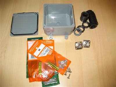
This is a picture of some of the parts for the project. I used a weather-proof enclosure because I didn't want to worry about sealing the ends of the coaxial cable and the connectors and it makes it a compact stand-alone device.

Another picture of the electrical box with the holes for the connectors already drilled.
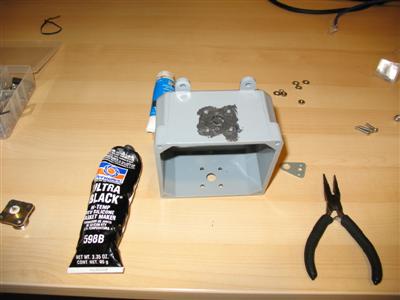
I used a non-corrosive RTV silicone to form a seal between the female N-connectors and the enclosure.
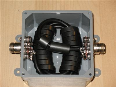
This picture shows the box with the connectors installed and the actual choke assembly. The choke is made of 18 ferrite rings organized in a "binocular core" of 2 rows by 9 rings and it has 3 and a half turns of coaxial cable thru the core. One turn counts as the cable passes thru both rows of rings. With 3 and one half turns the cable exits the core from the opposite ends. The inside diameter of the rings (18 mm) is just big enough to fit 4 turns of the cable and the spacing between the two ferrite "tubes" allows for the bend radius of the cable to be above the specified minimum bend radius of 3/4".

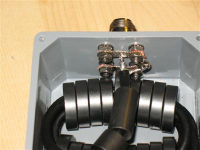
Since the ground connection to the bulkhead Type-N connectors is provided only by the 4 stainless steel screws (because of the plastic enclosure), I wanted to make sure that the ground connection is very good. I used 4 pieces of de-soldering braid to form a "bridge" between the screws and then used washers and nuts to attach the "bridge". I also made a connection point for the coaxial shiled by using two ring terminal connectors on each side. Then I "soaked" the braid with solder and soldered the ring terminals to each other. With this approach, all of the 4 screws are grounding the connector to the braid of the coaxial. Alternatively, one can use copper tape (or even better - tin plated brass sheet) to bridge all screws. I just didn't have any stock at the time.
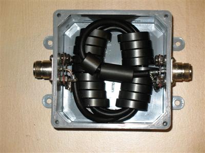
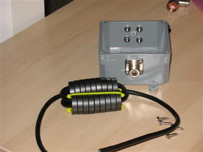
The already assembled choke. I used two more ferrite beads on the looping coaxial to improve the attenuation in the upper frequency range. More ferrite never hurts! Don't trust any lightweight ferrite chokes :-). I was limited by just how much ferrite I was able to fit in the box.
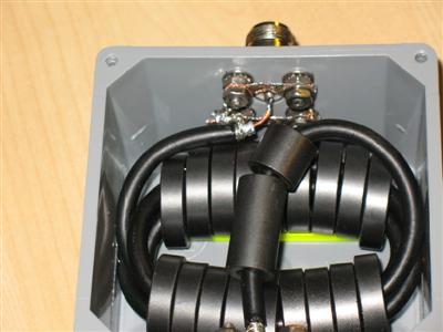
Close-up on the coaxial connection points. I, later treated the ends of the coaxial with "Liquid Electrical Tape" (just in case any moisture gets in).
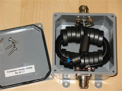
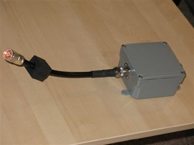
The choke is ready to be closed. The finished choke has a very clean and professional look.
for questions and comments about this article - ae1s AT arrl.net