(Click on the thumbnails for high-resolution image. Use the BACK button of your web browser to go back to the 80m coil page)
SteppIR are offering loading coil option for their BigIR antenna. This coil is installed at the base of the antenna (it is mounted on the EHU) and turns the antenna into a bottom loaded vertical antenna (for 80m and 60m bands only). With the extra loading the antenna covers frequencies from under 3.500 MHz up to 6 meters. The way the coil is connected is standard for bottom loading - in series between the feeder and the radiating element. The coaxial feed line is attached to the coil along with the ground radial system. The ground radial connector of the EHU is no longer in use and it is RF hot (!). The output of the coil is connected to the RF connector of EHU. The coil has 5 taps - 4 for 80 meters and one for 60 meters. The taps are selected by a 6-position Roto Switch (located right on the PCB) using stepper motor powered by the control box in the shack. Switching is done by rotating arm with 2 contact points attached to the shaft of the stepper motor. Position #1 is the coil bypass mode for 40m and up, positions #2 to #6 are the coil taps for 80m and 60m. The antenna controller selects the proper tap (and amount of inductive loading) according to the selected band and frequency. Fairly simple and straight forward design - no magic here.
At the end of July I ordered the 80 meter coil equipped with N type RF connectors. This time I made sure that they took my order correctly to avoid installing the N connectors myself (as it was the case with the EHU). I was told "8 to 10 weeks lead time" .To cut the long story short - (prospective buyers : Do not trust the waiting period projected at the time of the order!) the waiting was over 18 weeks (!). I was afraid that I'll need a snow-blower to get to the antenna site when the time for installation comes. It is the longest period of time I have ever waited for an ordered product to be delivered! My credit card was charged about a week before shipment.
The box was delivered by UPS at the beginning of December.
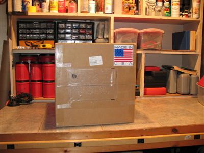
Here is the shipping box on the work bench in my garage. The box is proudly displaying "Made in USA" sticker.

The content of the box. Everything was very well packed in plastic wrap and "styrofoam noodles".
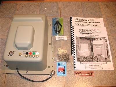
Loading coil, extractor tool for the firmware chip, bag with stainless steel hardware, 4 plastic spacers, terminal block, new firmware chip version 4904 and new sticker for the control box buttons, bag with dielectric paste and set of manuals.
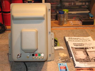
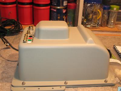
More views of the coil. Clearly visible are the RF connector, radial system connection point and the control cable terminals . The big flat housing cover is another candidate for transparent plexiglass modification. The enclosure of the loading coil is quite large - at least two times bigger than the EHU.
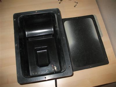
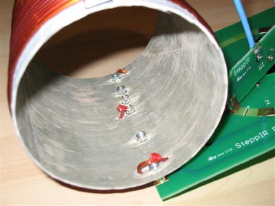
This the inside of the empty coil housing. The cover is using the same type of closed-cell foam gasket as the EHU. The output pigtail of the coil (seen at the bottom of the picture) is actually a heavy gauge stranded wire with very thick insulation (not coaxial) - the OD of the cable is the same as RG-8X. The male N connector is installed onto the cable in a way that both - the center pin and the the outside shell are connected to this wire, making the ground screw of the EHU RF hot!
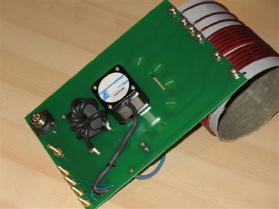
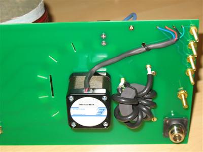
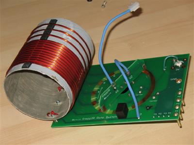
The back side (the side facing away from the antenna) of the coil assembly. N connector, brass screws for terminals, current balun, the stepper motor and the back side of the coil tap points.
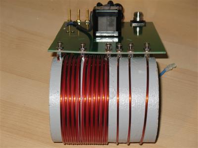
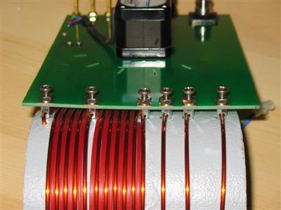
The actual loading coil with the tap points. Left to right - first tap - the beginning of the coil winding, tap #2 - 5th turn, tap #3 - 11th turn (the total length of the winding up to the 11th turn is 58 mm), tap #4 - 12th turn, tap #5 - 13th turn tap and tap #6 - 14th turn tap ( the end of the winding). Position #1 of the roto-switch is "by-pass". Positions #2 to #6 are corresponding to the coil taps in the order above. The controller firmware displays these positions as #0 to #5
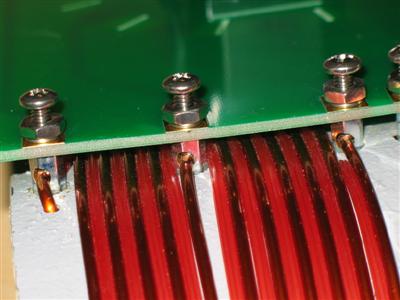
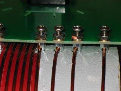
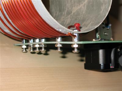
The coil taps hardware is made of stainless steel. The taps are actually terminal posts with the wire going thru the hole of the post and a screw making contact with the PCB and pressing against the wire at the same time. Very clever solution. The ends of the terminal posts are protruding thru holes in the coil form for mechanical support. The coil wire is of very heavy gauge (AWG 10, ~2.7mm diameter) and the turns are spaced about 3 mm apart for the first 11 turns by an interlacing nylon cord (something like the nylon cord from a Weed whacker) and then spaced 11 mm by small self-adhesive pads (used as stick-on feet for home electronics equipment) for the last few turns. The ends of the wire are bent inside the coil form and the ends of the nylon separator cord are melted into small blobs. The coil form looks like it is made of fiberglass-epoxy composition (I guess also made in-house) and it doesn't look very pretty - actually looks bad and unsightly - very rough outside surface and poor (flaking) paint. It appears to be very light and strong though. The look is not important - it does the job fine. The OD of the coil form is ~112 mm.
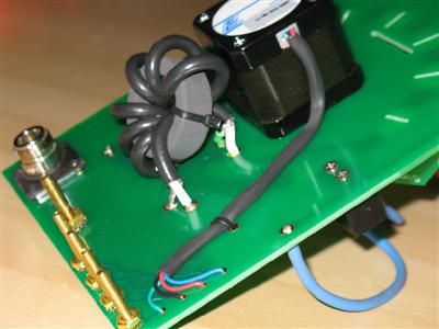
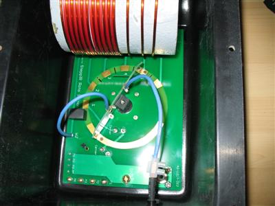
There is a large ferrite toroid making the common-mode current choke. 7 turns of small diameter coaxial cable (RG-58?). The stepper motor is connected directly to the 4 brass terminal screws. The brass screws are soldered on the front side to the PCB and brass nuts and lock washers are used on the back as spacers. The N connector has a thin rubber gasket.
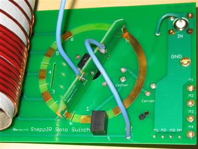
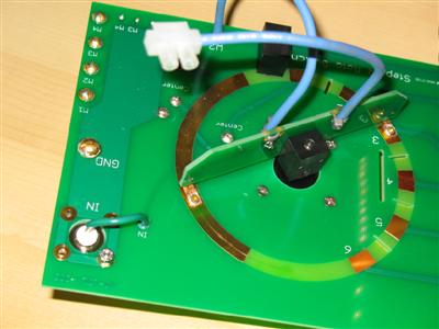
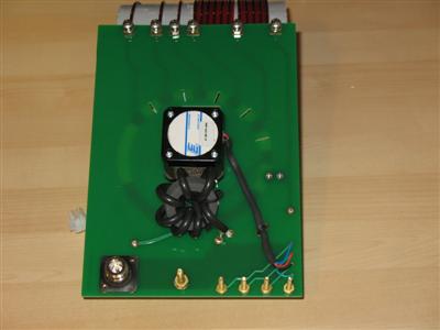
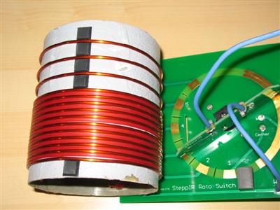
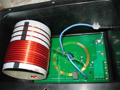
The Roto Switch is on the front of the PCB. The blue wire with the terminal block is connected to the output pigtail. The small black plastic block is a fixed calibration stop for the rotating arm. It stops the arm at Position #1 (bypass). The rotating arm is attached to the shaft of the stepper motor with similar in size plastic block and set screw. The rotating arm is made from PCB and has two copper-beryllium springs with gold plated contact points. The static portion of the contacts are etched on the main PCB and are gold-plated. The roto-switch looks solid and well made.
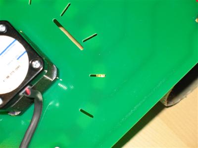
One of the gold-plated contact point is barely visible thru one of the several slits on the PCB (located between the static contacts).
5 self-adhesive rubber feet are used to separate three of the turns of the coil and to keep the coil winding in place. They also provide extra mechanical support for the coil form when the cover of the housing is on.
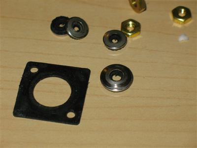
Well-made thin rubber gasket for the N connector along with some rubber-lined washers used to seal the brass terminal screws for the ground connection and the control cable. The washers are slightly cone-shaped with rubber seal on the bottom side and pressed by brass nuts. They should not be over-tighten!!
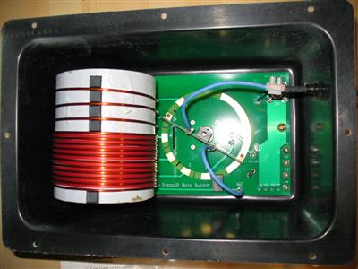
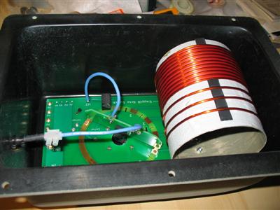
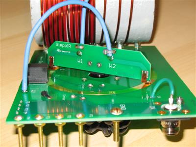
The PCB with the coil mounted in the coil housing. The enclosure is made of the same plastic as the EHU and painted the same way. The PCB is attached to the enclosure only by the brass terminal screws (4 for the control cable and 1 for ground) and 2 of the screws on the RF connector. Nothing else is used to secure the PCB and coil inside the enclosure. The coil form is a tight fit and when the cover is installed, the cover presses against the 5 small rubber feet on the coil (used to keep the winding in place and properly separated). This provides some additional mechanical support.
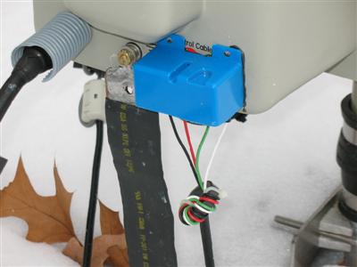
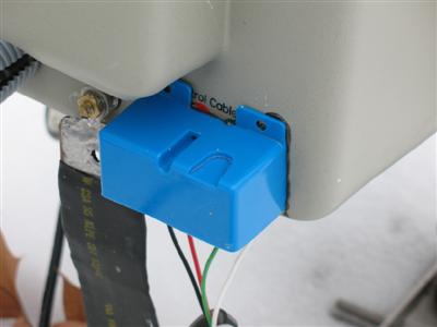
This is my "less than a dollar" ice/snow guard for the control cable terminals. Unfortunately SteppIR decided to use brass screws as terminal points for the control cable instead of a real water-proof connector (like the one used on the EHU). Cheap and simple from manufacturing point of view solution, but hardly the best one. Especially since the driver chips are unprotected against short and excessive current. Ice or snow build-up during extreme weather conditions could cause troubles for the control box and the operation of the coil. Furthermore one can accidentally shorten the terminals while working on the antenna or radial system. The manual talks about the use of RTV silicone to protect the terminals but this makes it look messy, unprofessional and the silicone is hard to remove from the terminals when needed. Ideally a water-proof connector should be used as the best way to modify the coil. I decided to put a "quick-n-dirty" terminal ice-guard. I used $0.89 electrical box from Home Depot. Cutting the electrical box about 1/4 from one end and used tiny amount of non-corrosive RTV silicone around the edge to attach it to the coil enclosure.
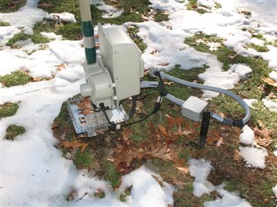
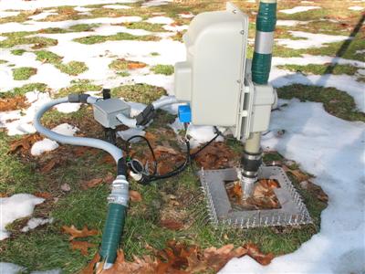
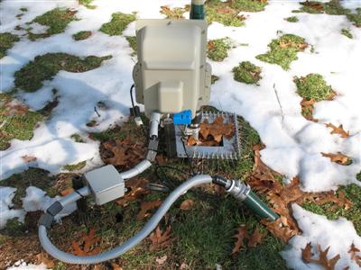
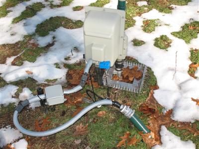
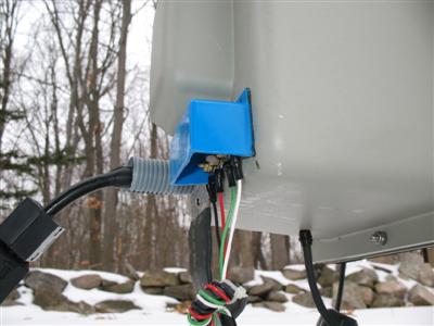
The installation of the coil was very simple. I had to remove 4 of the stainless steel screws from the EHU and used the supplied (longer) screws along with the plastic spacers. The coaxial line is connected to the coil, the output of the coil goes to the EHU. The radial system was disconnected from the EHU and connected to the ground lug of coil housing. My control cable was prepared beforehand so the only thing I needed to do is to form a small choke using a mix 43 toroid and connect it to the coil. I had also to move the location of the small plastic stake supporting the main common-mode current choke and heavy coaxial cable.
for questions and comments about this article - ae1s AT arrl.net